
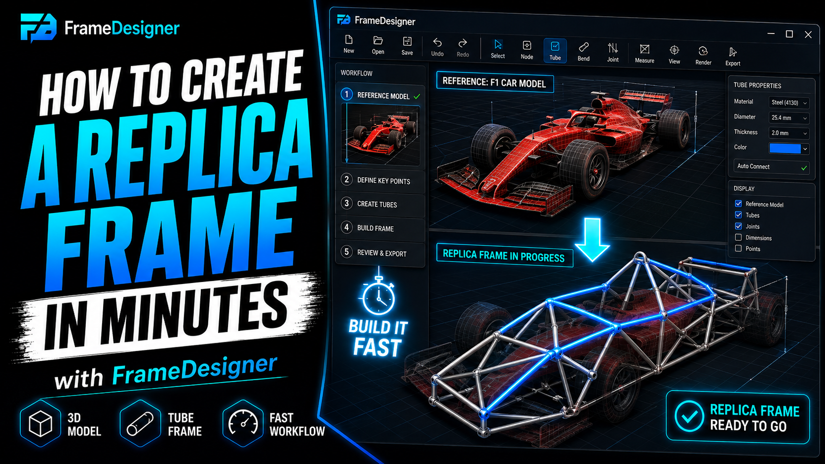
FrameDesigner exists because of a packaging problem I couldn't solve on paper.
I was designing a tubular frame around components that already existed — an engine with its own bolt pattern and its own idea of where the exhaust ports point, wheels at a wheelbase I'd already committed to, a driver who needed somewhere to put his legs. There was no drawing set. There was a pile of real objects and a requirement that a frame fit around all of them.
CAD will model that. That was never the issue. The issue was how much of my time went into translating — between the way CAD wants to think and the way the guy at the bender needs to be told things.
Which is a polite way of saying I spent a lot of evenings copying numbers out of one window and typing them into another, and I got some of them wrong. The wrong ones were never wrong randomly. Every single time, something upstream had moved — a joint nudged 8 mm to clear something, a bend radius changed because the die I'd assumed turned out to be a different die — and the number I was working from had been correct before that change and was quietly not correct afterwards. There's no error message for that. You find out when a tube is short, and by then you've also cut the three members you derived from the same stale sketch.
A builder is every department at once
A manufacturer has separate people for CAD, structural analysis, manufacturing drawings, fixturing, CAM and fabrication. Six job titles, six sets of software, and a process for handing work between them.
In a garage that's one person on a Saturday. Same person measuring the engine at nine, designing a cross-member at eleven, printing a notch template after lunch, ordering steel on their phone, and welding by evening. Nobody hands anything to anybody.
That changes what the software should be good at. The interesting question isn't "can it draw a tube." It's whether it can get you from the thing in your head to a tube you can actually cut, without you doing the translation by hand in the middle.
Tubes are harder than they look
A spaceframe looks trivial. Tubes, joints, done. Then you start building one.
Tubes have real wall thickness, so a joint isn't two centerlines crossing — it's a physical cut with a specific shape. Bend radius changes where the tube ends up and how much stock it consumes. Two bends on one member means clocking, and clocking is how you produce a part where every dimension is correct and both ends point the wrong way. A reference model can look completely convincing and be 4% undersized. A simulation can run clean and mean nothing if you fixed the wrong nodes.
None of that is optional detail. It's the difference between a part that fits and a part you cut up for brackets.
Design around the real object
The first thing that had to work was reference geometry. Import the engine, the body, the seat, the whole donor car if you have a scan of it — then build around volumes that genuinely have to fit, rather than designing in empty space and finding out later.
Reference models stay dimensionally separate from the frame, so you can scale, rotate, reposition and hide them without disturbing geometry you've already drawn. Hide the body shell to reach the inner structure, bring it back to check clearance. That sounds minor. It's most of the workflow on a replica or a one-off, where there's no complete drawing set to start from and the bodywork is the specification.
Make the tube know things
A member isn't a cylinder between two points. It has material, OD, wall, joints at each end, bends along its length, and a relationship with everything it touches.
Once that's true, the rest follows on its own: notch geometry per end, developed lengths, printable flat patterns, a fabrication order, structural simulation, STEP out to whatever you're doing brackets in. Same idea extended to exhaust work, where the routing problem is ports, collectors, bend geometry, equal lengths and heat all fighting over the same cubic foot.
Who this is for
The most interesting fabrication I see isn't happening inside large companies. It's garages, two-man shops, university teams, makerspaces, club racers, home machinists.
Those people are frequently excellent and have to be ruthless about software. A package that costs thousands a year, wants a workstation, and assumes you have a CAD department can be superb and still be the wrong tool. The assumption here is the opposite one: this should be usable by someone standing next to the bender with dirty hands.
Which is also why there's a free tier that does real work rather than a demo that teases you. You should be able to build actual geometry, see the fabrication output, and decide whether it suits how you work before any money changes hands.
What early users have changed
Builders have already pushed the product around, mostly by showing me where real workflows diverge from what looks obvious on a feature list.
A thing can be mathematically correct and still awkward on a shop floor. A render can contain all the geometry and still be unreadable. A simulation can solve and still need a better picture to be worth anything. A reference model can load perfectly and be infuriating if hiding parts doesn't behave the way your hands expect.
That feedback is worth more than roadmap planning, because this isn't trying to be a generic CAD package in a browser. It's trying to do one narrow thing properly.
Why there's a blog
Partly to document the process. Some of what goes here will be engineering explanation, some will follow actual builds, some will be features in progress, and some will be mistakes — the gap between what the screen said and what came off the bender.
The articles aren't meant to be marketing pages with a tube on them. The point is a library that explains why the measurements, the bends, the notches and the simulations work the way they do, which is useful to you whether or not you ever open the software.
One thing I'd rather say plainly than bury: software makes engineering faster, it doesn't transfer responsibility. A cage is a life-safety structure. Validation, material certification, weld quality and sign-off by qualified people where the rules require it are still on the person holding the torch.
If you build something with it, I want to hear what slowed you down and what output would have saved you the most time. That goes through the support page and I read all of it.
Comments
Loading comments…