
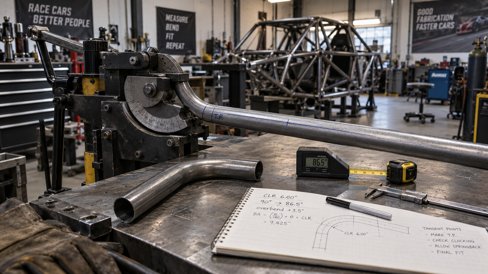
Parts that don't fit almost always fail on one of four numbers. None of them is hard. All of them are easy to get wrong in a way that stays invisible until the tube is on the table and 11 mm short.
1. Centerline radius
CLR is the distance from the center of curvature to the axis of the tube. It belongs to the die, not to your design.
The mistake people make is confusing it with the inside radius of the bend. They differ by half the OD:
CLR = inside radius + (OD ÷ 2)
A die sold as a "4 inch radius die for 1.75 tube" could mean either one. The gap between them is 0.875", which is plenty to make a chassis member miss. Don't trust the label. Bend a test piece, measure it, write the number on the die with a paint pen.
You'll also see benders described in D of bend — CLR divided by OD. A 3D bend in 1.75" tube is a 5.25" CLR. Below about 2D things get unpleasant: the outside wall thins, and without a mandrel you're flirting with collapse.
And this is worth being blunt about. In a home shop CLR is not a design variable. You own the dies you own. Measure what each one actually produces, write those numbers down somewhere permanent, and treat them as fixed inputs to every frame you ever draw. Designing a 150 mm CLR when the only die on the bench is 175 mm means the part cannot be built, and you find out after the material arrives.
2. Bend allowance
A bend eats tube, and it eats less than the square corner it replaces. Bend allowance is the arc length along the centerline:
Bend allowance = CLR × degrees × 0.01745
The constant is just π/180.
So a 90° bend on a 6" CLR consumes about 9.42" of tube. Cut length for the whole member is the straights plus one bend allowance per bend. That total is your developed length, and it's the number you order stock against.
Then there's setback: the distance from the tangent point — where the bend starts — out to where the two straight sections would have crossed if they'd kept going. For a 90° bend, setback equals the CLR.
That one causes real trouble, because your drawing dimensions go to the theoretical corner while your marks on the tube have to sit at tangent points. Mark from the wrong reference and every part comes out wrong by the same amount, which is somehow more confusing than random error. You'll check the math three times before you question the reference.
3. Springback
Bend to 90°, let go, and you don't have 90°.
Bending stretches the outside and compresses the inside. Release the ram and the elastically strained material tries to go home while the plastically deformed material won't. What you end up holding is the argument between them.
There's no formula worth using. Springback moves with material grade, wall, diameter, die, machine, and how your pressure die and mandrel are set. Published tables are a starting guess. Two sticks of tube with identical mill markings from different heats will not behave the same.
So do it empirically:
- Bend a test piece — same material, same size, same die — to 90°.
- Release and measure what you've actually got. Say 86.5°.
- That 3.5° is your springback for that combination.
- Overbend by it from then on. Pull to 93.5° to land on 90°.
Keep the numbers on a card per material and die, taped to the bender. Re-test when new stock shows up. Ten minutes of test bending is cheaper than one scrapped 1.75" DOM main hoop, and it isn't close.
4. Clocking
Clocking is how far each bend is rotated about the tube axis relative to the one before it. Flat part, every bend in one plane, clocking is zero. The moment a member goes out of plane, each bend has to be rotated by a specific angle before you pull it.
This is the one that produces the baffling failures, because every individual dimension on the finished part can be dead right and the part is still garbage. Lengths correct. Angles correct. Both ends pointing somewhere you didn't ask for.
It's also hard to catch in progress. A tube with two bends looks about right from most angles whether or not the rotation between them is correct. You find out when you offer it up.
Three defenses: work from a bend sequence that states the rotation explicitly rather than inferring it; scribe a rotation reference line down the length of the tube before the first pull; check against the model after each bend rather than at the end, when the only remaining options are heat and prayer.
Why you'd let software hold these
None of this arithmetic is difficult. What makes it error-prone is that the four numbers interact, and that every one of them moves when the design moves.
Nudge one joint. Straight lengths change. Developed length changes. Tangent points relocate, so every mark on the tube changes. Do that across forty members by hand, through six design revisions, and transcription errors aren't a risk you're managing — they're a thing that has already happened and you don't know where yet.
Tools that recalculate the whole chain when geometry moves are solving that, not the arithmetic. The arithmetic was never the hard part.
Springback is still yours, though. No model knows what your bender does on a Tuesday. That one stays a test piece, a protractor and a card on the wall.
Comments
Loading comments…